You might think ham radio is all about the radios, but it’s really about the antennas. That becomes apparent when you move into the long-distance HF bands, where having the right antenna type at the right length with ideal placement makes all the difference. You can have a fantastic 100-watt HF transceiver like the Icom IC-7300, but if you’re using a coat hanger for an antenna, you’ll struggle to make contacts. On the other end, an optimal antenna with a 5-watt QRP radio can make contacts all over the world.
Jason Oleham, call sign KM4ACK, has become an invaluable source for emergency communications thanks to his Build-A-Pi software and his helpful YouTube channel. He sells a popular end-fed half-wave (EFHW) antenna kit in his store that is frequently out of stock. Is it worth the hype or are hams buying it for the brand?
I’ve loved electronics ever since I can remember. The only problem is I’m terrible at soldering, which has always felt like a black art to me. Despite that, I was interested in trying my hand at assembling this antenna and it seemed simple enough. What finally pushed me over the edge was a YouTube reviewer saying the KM4ACK blew away his Chameleon EMCOMM-III portable EFHW, which is the antenna I’ve been using. The Chameleon is $160 while KM4ACK’s kit is only $40, so I had to check it out.
Building your own antennas is a rite of passage in the ham radio field, and having the skill to do so makes you that much more self sufficient. Plus, building your own antennas is cheaper than buying them.
The hard part is finding the kit in stock. I recommend clicking the “Get notified when the kit is back in stock” link to sign up for an email notification. You can buy the antenna with either a BNC connector (for small, low-power QRP radios) or SO-239 (standard antenna connector), and the choice depends on what your radios use (you can always buy adapters if you must).
I also recommend adding some extra capacitors to your order as cheap insurance in case you break the one included or burn it up with the soldering iron.
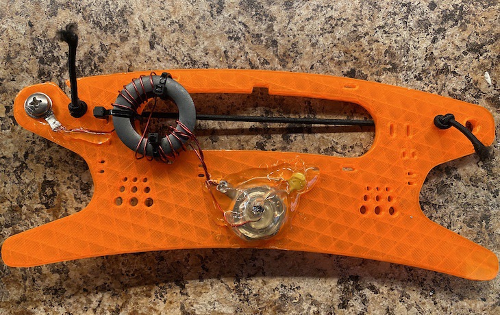
What’s in the package and what you need
The kit comes with all the hardware you need, except rope to hang the antenna in the tree. It includes:
- A 3D-printed wire winder that acts as the antenna’s “body”
- Ferrite ring and magnet wire for wrapping the toroid
- Connector, either BNC or SO239
- 67 feet of antenna wire
- Dogbone wire insulator for the end of the antenna wire
- Elastic string to hold the wire in place on the winder
- Zip ties for attaching the toroid to the wire winder
- Stainless hardware for attaching the antenna to the winder
You’ll need some basic electronics tools to assemble the antenna. If you don’t already own these, they’re good investments to make that will carry you through numerous electronics projects and electrical repairs:
- Soldering iron and solder
- Multimeter
- Crimper (can probably get by without this if you have a good pair of pliers)
- Pliers
- Wire strippers
- Wire cutters
- Lighter or heat gun
- Sandpaper
- Hot glue gun
- Wrenches
- Coaxial cable
I linked to some of the tools I use in the above list.
Assembly
Jason has an outstanding assembly video that is clear and concise even for beginners. I won’t repeat it all here, but I’ll offer some insights and opinions on different stages of the process. Someone experienced with electronics should be able to get the antenna built in about an hour. Assembly might not take that much longer for the inexperienced, but you may spend more time troubleshooting and redoing steps.
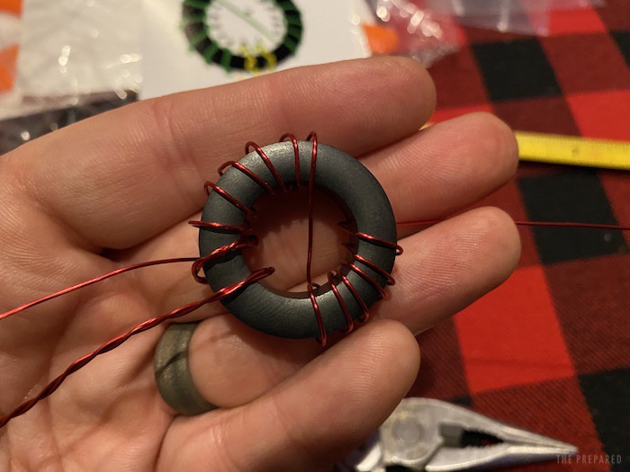
When I first reviewed the assembly instructions, I assumed that winding the toroid would be the fussiest part. In reality, it was one of the easier steps, just follow the instructions and diagram, go slow, and pull your wraps tight against the ferrite ring.
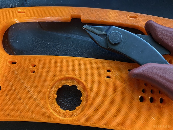
My first stumbling block was altering the winder’s connector hole to accept the SO-239 connector. The winder is designed with BNC in mind and some of the plastic must be removed to accept an SO-239 connector. What I found worked well was to use my wire cutters to clip out the plastic sections.
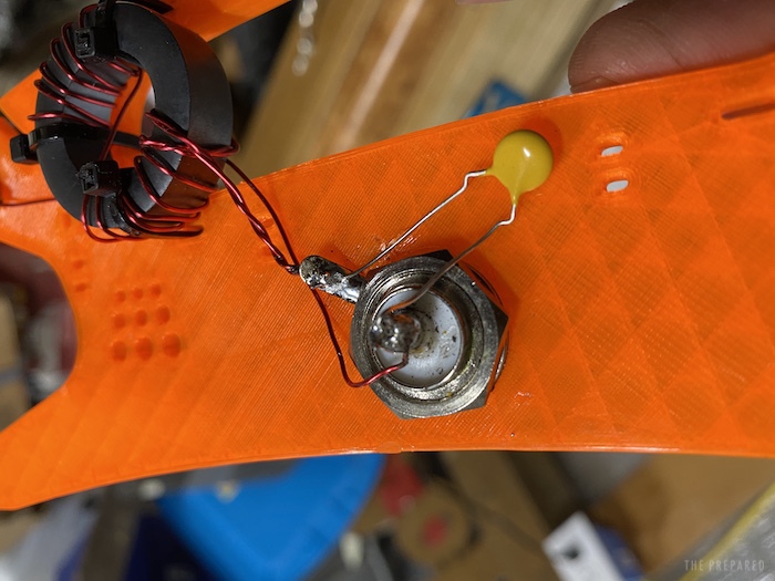
Jason tells you to get the antenna connector good and tight but doesn’t really explain how. I learned the hard way that you want it tight, which I’ll get to below, but here’s the trick I figured out. On the opposite end of the connector is a large nut, which requires a ¾-inch wrench or socket. But no matter how much you turn that nut, it won’t get tight unless something is applying tension to the other end. You don’t want to put pliers or anything on the connector or you’ll damage the threads. The trick I figured out is to screw a coaxial cable onto the antenna connector and then tighten the nut. Before going further, attach and detach the cable a few times to make sure the connector is firmly in place and won’t spin around.
The other problem I had: after soldering all the connections, I only had continuity in 2/3rds of the points he says to test. I spent a few days puzzling over it. At one point I assumed I had overheated the capacitor. So I ordered a set of spares along with a spare coax connector. But that wasn’t it either.
I ended up desoldering the whole thing, and I discovered that on the pair of twisted magnet wires soldered to the ground lug, only one of the wires actually got soldered. Resoldering solved the problem.

After everything is soldered and tested, Jason recommends burying the main assembly in hot glue to protect it against the elements. This is a good idea, but I recommend against doing so until you’ve successfully tested the antenna in the field. If I had hot glued it at this point it would have ended in disaster.
While I’m still not great at soldering, this project helped me get plenty of practice. I’ll offer a few tips:
- Why does solder sometimes glob up and not flow over the metal? The answer is oxidation from high heat in contact with the metal. The solution is a chemical called flux, which protects the metal from oxidation and allows the solder to flow freely. Most solder has some flux baked in so you don’t have to apply extra. If you have to resolder a joint, you might find that the old solder doesn’t do what you want until you apply fresh solder. That’s because the flux was burnt off of the old solder, and the flux in the fresh solder helps make the joint. It’s good to have some flux in your solder kit, as an application resolves most soldering issues.
- You want to make a good mechanical connection before soldering, both to keep stress from the solder joint over the long haul and to make a good joint that is shiny and smooth and not grainy. You see examples of this in Jason’s video, where he crimps a wire in place and then solders it. The crimp holds the wire and keeps stress off the joint when the wire is pulled. When you solder the twisted wire and the capacitor leg to the ground lug, it’s best if you put them through the ground lug hole to help hold them in place.
- Your solder joint should be shiny and smooth. If it’s rough and grainy it’s a cold joint and will likely break in the future. It most often happens because a part moves during the soldering process, which is one reason why you want a good mechanical connection.
One step forward, two steps back
With everything assembled and the weather finally clear, I was finally able to hang the antenna and give it a go. Everything tested great, and I was ready to bring it in and hot glue it. Until I tried to unscrew the coax cable from the antenna. The threads were stuck tight and the antenna connector was spinning around. The magnet wire and capacitor lead soldered to the center pin wrapped around it and broke. I finally broke the coax cable free with a wrench and promptly went back to the drawing board.
That’s when I figured out the trick of connecting the coax cable to the connector before tightening it. Once it was tight enough that I could repeatedly screw the cable on and off without anything budging, I plugged in my soldering iron.
I might have reused the capacitor, but I decided to use one of the spares I had ordered so the leads would be long enough to let the capacitor lay flat on the winder. I was pretty pissed at the time, so this wasn’t my best soldering work. I melted the blob of solder in the center pin and quickly jammed the capacitor and magnet wire inside before it solidified, and then I soldered the other end of the capacitor to the top of the ground lug because I didn’t want to unsolder the twisted pair. Besides, the entire thing would get covered in hot glue. It all checked out on the multimeter, so I reconnected the antenna to test.
Testing vs. the Chameleon
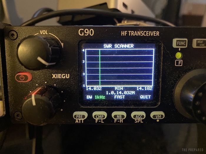
There are a few ways to test an antenna. The standard is an SWR meter, which tests the antenna’s resonance on certain frequencies. The ideal measurement is 1:1, which means the antenna works at maximum efficiency on the chosen frequency and thus the radio doesn’t have to work as hard.
SWR meters are expensive, which is part of why I opted for the Xiegu G90 as my first HF transceiver, since it has one built in. Jason claims the antenna is resonant on 10, 15, 20, and 40 meters. 20 and 40 are probably the most popular bands and the ones I use most often.
I used my G90’s built in SWR meter on all four bands, and all read pretty close to 1:1, which is pretty impressive and better than my Chameleon, which often read 2:1. I tried 80 meters, another band I use often and it was over 4:1, making the KM4ACK antenna useless on that band, but again, Jason doesn’t claim it works on that band. The Chameleon is equally mediocre on 20, 40, and 80. I think all tests being the same, I’d rather have the better performance on a more limited set of bands.
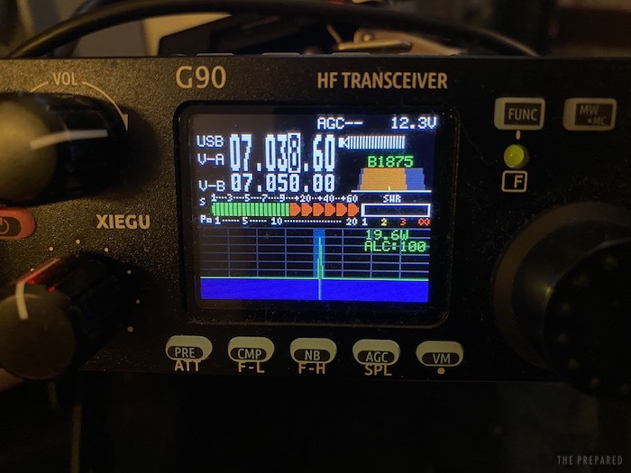
But SWR only tells us if the wires are working well, they don’t tell us how well the antenna and its placement is making contacts. For that, I use a protocol called WSPR, short for Weak Signal Propagation Reporter, through the WSJT-X software package.
WSPR works in two-minutes cycles of listening for and transmitting small packets of data at 5 watts of power. You can then view a map that shows what other WSPR stations heard your transmission. HF propagation depends on sun cycles, time of day, and other factors, but it gives you a real-world look at how well your rig is doing.
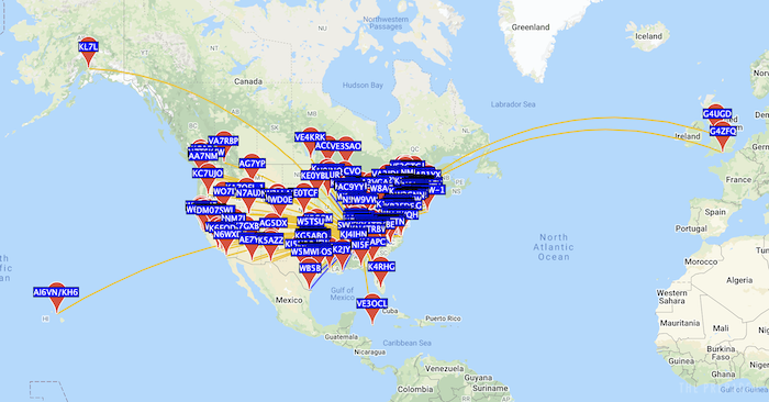
As you can see, I get pretty good coverage with this antenna at only 5 watts, reaching all the way from Hawaii to Ireland.
Hot glue
After some more testing with JS8Call, I was happy that the antenna was functioning as intended and any other optimizations would come from placement or adjusting the length of the antenna wire. So I broke out the hot glue gun and buried the wires and electrical components in a thick layer of hot glue. If I’d done that before I discovered that the coax connector was tight enough, I’d have a nightmare on my hands. But now the electronic components are thoroughly protected from the elements.
The KM4ACK EFHW as your first antenna?
If you’re a seasoned ham, you’re already pretty interested in the KM4ACK antenna. It’s cheap, easy to assemble, lightweight, and doesn’t need a tuner on four bands. That’s an unbeatable package for portable operations. And if you haven’t taken the step of building an antenna yet, this is a great way to start.
But if you’re new? This is a great antenna and a great first antenna project where your hand is held through the entire process. That said, when you’re new and shaky, you may prefer something that just works out of the box. The Chameleon EMCOMM-III is a well-regarded antenna that is portable, versatile, and built like a tank, but at a steep cost. It’s served me well for over a year.
There’s no such thing as a perfect antenna. They all have trade-offs and most hams end up with several in their arsenal for different purposes.
You are reporting the comment """ by on